
Underfloor heating system design is represented in AutoCAD drawings through coordinated layout plans, manifold schematics, pipe routing details, zoning diagrams, construction layers, and installation specifications. These drawings provide a visual framework that enables engineers, designers, contractors, and facility teams to implement heating systems accurately while meeting performance, safety, and energy-efficiency requirements.
In modern commercial buildings, underfloor heating has become an important component of HVAC and plumbing design. Industries such as healthcare, hospitality, education, and commercial real estate increasingly adopt radiant heating systems because they improve thermal comfort, reduce visible equipment requirements, and support energy management strategies. Accurate AutoCAD documentation ensures that every stakeholder understands how the system functions before installation begins.
What Is Underfloor Heating System Design in a Building Services Environment?
Underfloor heating system design defines the arrangement of heating pipes, manifolds, zones, controls, and heat distribution requirements within a building. AutoCAD drawings transform engineering calculations into visual documentation that supports planning, installation, commissioning, and long-term facility management.
Underfloor heating is a radiant heating method that transfers heat through pipes installed beneath finished floor surfaces. Instead of relying on conventional radiators, heat spreads evenly across occupied spaces. This approach creates consistent indoor temperatures and improves energy utilisation.
From a business perspective, underfloor heating design supports building performance objectives. Organisations seek thermal efficiency, reduced operational costs, and improved occupant comfort. Commercial buildings often measure HVAC performance through KPIs such as energy consumption per square metre, temperature consistency, maintenance frequency, and system lifecycle costs.
AutoCAD drawings serve as the communication platform between design teams and installation teams. Every pipe route, manifold location, room zone, and control connection is represented graphically to eliminate ambiguity during construction.
How Does AutoCAD Represent Underfloor Heating Layouts?
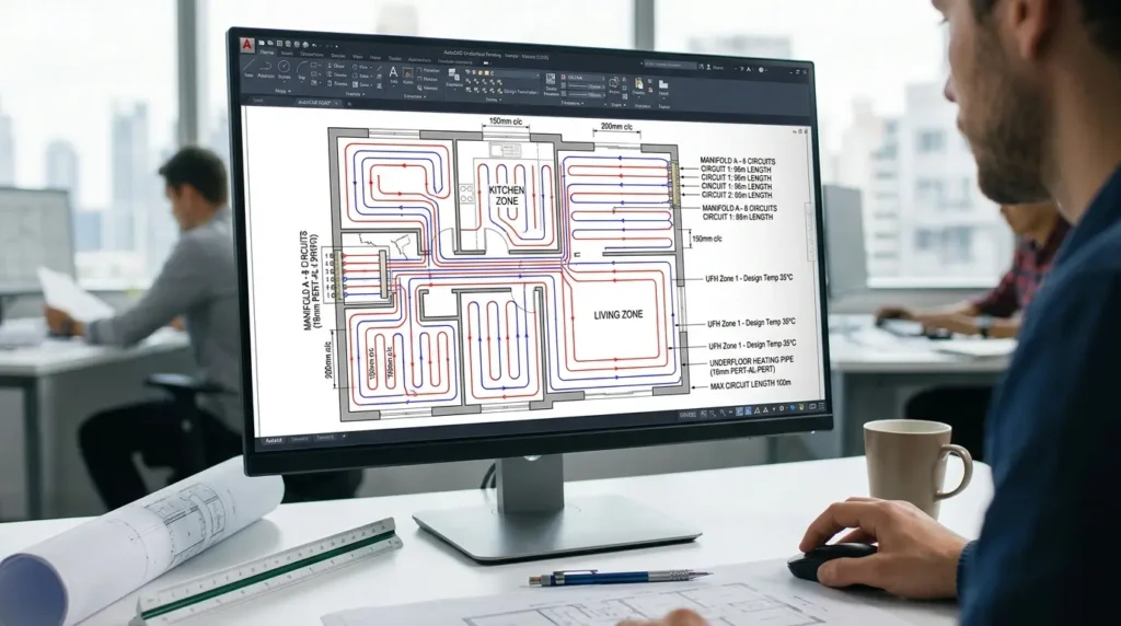
AutoCAD represents underfloor heating layouts through scaled floor plans showing pipe circuits, spacing intervals, manifold positions, flow directions, zone boundaries, and reference dimensions. These drawings provide installation teams with clear instructions for implementing heating systems across multiple building areas.
The layout drawing forms the foundation of the design package. Engineers begin with architectural floor plans and overlay heating circuits according to thermal load calculations.
Pipe layouts typically appear as continuous loops distributed across rooms. The spacing between pipes is determined by heating requirements. Areas with higher heat loss require tighter spacing. Areas with lower heating demand use wider spacing patterns.
The drawing also identifies circuit lengths. Maintaining consistent circuit lengths improves hydraulic balance and system efficiency. Commercial projects often include dozens of heating circuits connected to multiple manifolds.
Annotations within AutoCAD drawings identify pipe sizes, flow rates, design temperatures, and installation notes. These elements ensure that construction teams understand design intent without relying solely on written specifications.
Typical Information Shown on Underfloor Heating Layout Drawings
A standard underfloor heating layout contains several technical elements:
- Pipe routing patterns
- Circuit numbering
- Room zoning labels
- Pipe spacing dimensions
- Flow and return connections
- Manifold references
- Construction grid references
- Floor finish information
- Heating load references
- Installation notes
Each element contributes to accurate system implementation and quality control.
How Do Manifold Designs Appear in AutoCAD Drawings?
Manifold designs are represented through schematic diagrams and detailed installation views showing circuit connections, control valves, flow meters, balancing devices, and distribution arrangements. These drawings coordinate hydraulic performance and system management requirements.
The manifold acts as the central distribution point of an underfloor heating system. Multiple heating circuits connect to a manifold assembly, allowing balanced water distribution throughout the building.
AutoCAD schematics illustrate how circuits connect to supply and return headers. Designers identify every circuit using unique reference numbers. These references correspond directly to the floor layout plans.
Control components are also represented visually. Examples include:
- Isolation valves
- Balancing valves
- Thermostatic actuators
- Pressure gauges
- Flow meters
- Drain points
Facility management teams rely on these drawings during maintenance and troubleshooting activities.
Large commercial developments frequently contain multiple manifolds serving different zones. AutoCAD documentation ensures that all manifolds integrate correctly with the broader HVAC and plumbing infrastructure.
How Does the Design Process Work Before Drawings Are Produced?
The design process begins with heat load calculations, space analysis, zoning strategy development, equipment selection, and system sizing. AutoCAD drawings are generated after engineering requirements have been verified against building performance objectives.
Underfloor heating design follows a structured workflow.
Engineers first evaluate building characteristics. Factors include room dimensions, occupancy levels, insulation performance, glazing ratios, and ventilation requirements.
The next stage involves thermal load calculations. These calculations determine how much heat each room requires to maintain target temperatures.
Once heating demands are established, designers develop zoning strategies. Zones allow independent temperature control across different operational areas.
Examples include:
- Office zones
- Meeting room zones
- Patient care zones
- Hotel guest room zones
- Educational facility zones
After zoning is complete, system components are selected and AutoCAD documentation begins.
This structured approach reduces design errors and improves project delivery outcomes.
What Skills Are Required to Create Underfloor Heating Drawings in AutoCAD?

Creating underfloor heating drawings requires proficiency in AutoCAD drafting, HVAC fundamentals, plumbing coordination, system calculations, construction documentation, and technical communication standards used across engineering and building services projects.
Many organisations identify skill gaps in technical drawing interpretation and HVAC system documentation. These gaps can affect project timelines, installation quality, and coordination efficiency.
For deeper insight enrol in:
AutoCAD HVAC and Plumbing Design Training Course.
Professional training programmes often address several competency areas:
AutoCAD Technical Skills
Participants learn:
- Layer management
- Annotation standards
- Block creation
- Drawing templates
- Plotting procedures
- Dimensioning practices
HVAC Design Knowledge
Participants study:
- Heat transfer principles
- Hydronic systems
- Pipe sizing fundamentals
- Zoning methodologies
- Control strategies
Documentation Standards
Participants learn how to produce construction-ready drawings that align with engineering workflows and project requirements.
In workforce development programmes, organisations frequently measure success through assessment scores, design accuracy rates, project completion times, and reduced drawing revision cycles.
How Is Underfloor Heating Training Delivered in Corporate Learning Environments?
Corporate training combines instructor-led workshops, online learning modules, practical exercises, project simulations, and competency assessments. Structured learning paths help employees apply AutoCAD and HVAC knowledge within real project environments.
Training delivery varies according to organisational objectives and workforce needs.
Instructor-led workshops focus on technical demonstrations and guided practice. Online modules support flexible learning schedules. Hybrid learning combines both approaches to improve accessibility and knowledge retention.
Many organisations adopt a phased training structure:
Phase 1: Technical Foundations
Employees learn HVAC principles, hydronic systems, and underfloor heating concepts.
Phase 2: AutoCAD Application
Participants create layouts, annotations, schematics, and coordinated construction drawings.
Phase 3: Project-Based Learning
Learners complete practical assignments based on real building scenarios.
Phase 4: Assessment and Validation
Competency assessments measure technical understanding and practical performance.
When organisations evaluate specialised implementation methods and drawing standards, readers often progress toward solution evaluation and technical training considerations.
This transition point aligns naturally with detailed learning resources such as:
How does AutoCAD HVAC training address underfloor heating layouts and manifold design?
What Components Are Included in a Complete Underfloor Heating Drawing Package?
A complete drawing package includes layout plans, manifold schematics, zoning diagrams, installation details, equipment schedules, construction notes, and coordination drawings that support implementation, commissioning, and operational management.
Construction projects depend on coordinated documentation.
Layout plans identify circuit arrangements. Manifold diagrams illustrate hydraulic distribution. Equipment schedules define technical specifications.
Coordination drawings are particularly important. HVAC systems interact with plumbing, electrical, architectural, and structural disciplines.
Examples of coordination requirements include:
- Structural slab penetrations
- Equipment room layouts
- Electrical control wiring
- Building management systems
- Plumbing service routes
Integrated documentation reduces clashes during construction and improves project efficiency.
What Business Benefits Do Accurate AutoCAD Underfloor Heating Drawings Deliver?
Accurate drawings improve installation quality, reduce construction rework, support energy efficiency objectives, strengthen project coordination, and enhance facility lifecycle management across commercial and institutional buildings.
Drawing quality directly influences project outcomes.
Poor documentation often results in installation errors, schedule delays, and additional costs. Accurate AutoCAD drawings reduce uncertainty throughout the project lifecycle.
Organisations frequently monitor measurable outcomes such as:
- Reduction in design revisions
- Faster project delivery
- Lower installation rework rates
- Improved commissioning performance
- Reduced maintenance interventions
These metrics contribute to stronger return on investment from engineering and construction activities.
From a workforce perspective, employees who understand HVAC documentation standards contribute to higher-quality project execution and improved cross-functional collaboration.
Which Industries Use Underfloor Heating Design Documentation Most Frequently?
Industries requiring thermal comfort, energy efficiency, and building performance management rely extensively on underfloor heating documentation for design, construction, and operational planning activities.
Healthcare facilities use radiant heating to maintain stable indoor environments.
Hospitality properties use underfloor heating to enhance guest comfort while reducing visible HVAC equipment.
Educational institutions integrate radiant systems into modern campus developments.
Commercial offices use underfloor heating to support flexible interior layouts.
Industrial facilities apply underfloor heating in specialised operational areas requiring controlled environmental conditions.
Across these sectors, AutoCAD remains a standard platform for creating and managing technical design documentation.
What Common Misconceptions Affect Underfloor Heating Design Training?
Common misconceptions include believing that AutoCAD alone creates effective designs, that installation experience replaces design knowledge, and that generic HVAC training covers specialised underfloor heating documentation requirements.
AutoCAD is a design tool, not a design methodology. Successful projects require both software proficiency and engineering understanding.
Another misconception assumes that installation teams do not need drawing literacy. In reality, installers, supervisors, and project managers rely heavily on construction documentation to execute projects accurately.
Some organisations also assume that general HVAC knowledge automatically transfers to radiant heating design. Underfloor heating systems involve specific considerations such as circuit balancing, manifold design, zoning strategies, and thermal performance calculations.
Targeted learning programmes address these specialised requirements through structured content, practical exercises, and measurable assessments.
How Does Underfloor Heating Design Support Organisational Performance Goals?
Underfloor heating design supports operational efficiency, sustainability objectives, facility performance management, and workforce capability development through structured engineering documentation and coordinated project execution.
Modern organisations increasingly prioritise measurable performance outcomes.
Building owners seek energy efficiency improvements. Facilities teams focus on maintenance optimisation. Project teams aim to reduce construction risks and improve delivery schedules.
Accurate AutoCAD documentation contributes to these objectives by creating a reliable information source throughout the building lifecycle.
Discover More from Our Guide Library:
What Tools in AutoCAD Help HVAC Designers Produce Accurate Take-Off Quantities?
How Is an AutoCAD HVAC Drawing Set Organised for Client Submission?
When technical teams understand how underfloor heating systems are represented, coordinated, and managed within AutoCAD environments, organisations achieve stronger consistency across design, construction, commissioning, and operational stages.
Underfloor heating drawings therefore represent more than graphical documentation. They function as a critical business tool supporting engineering quality, workforce competence, project efficiency, and long-term building performance.
Frequently Asked Questions
Who should attend an AutoCAD HVAC and Plumbing Design Training Course?
This course is suitable for HVAC engineers, plumbing designers, CAD technicians, MEP professionals, and construction project staff. Imperial Corporate Training Institute structures the training to support both new professionals and experienced personnel seeking to improve design documentation skills.
How does AutoCAD help with HVAC and plumbing system design?
AutoCAD enables professionals to create accurate HVAC layouts, plumbing drawings, piping schematics, and coordinated MEP documentation. It improves design accuracy, supports project coordination, and reduces drafting errors throughout the construction process.
Why is AutoCAD important for HVAC and plumbing projects?
AutoCAD provides a standard platform for producing technical drawings used in building services engineering. The AutoCAD HVAC and Plumbing Design Training Course helps learners understand how to develop clear, organised, and construction-ready documentation for commercial and residential projects.
What skills can participants gain from an AutoCAD HVAC and Plumbing Design Training Course?
Participants learn HVAC drafting, plumbing design fundamentals, equipment layout planning, drawing annotation, layer management, and technical documentation practices. Imperial Corporate Training Institute focuses on practical skills that align with current industry requirements and project workflows.