
Organisations involved in building services engineering increasingly require HVAC professionals who can move from concept development to installation-ready documentation. This requirement creates a common training challenge: understanding the distinction between schematic drawings and working drawings within an AutoCAD HVAC workflow.
Many learners first encounter HVAC drawings as visual representations of systems, but technical training focuses on the purpose, structure, and application of each drawing type. Before evaluating training approaches, it helps to understand the fundamental drawing categories explained in this guide on:
What Is the Difference Between Schematic and Installation HVAC Drawings? That foundation supports a more accurate assessment of how AutoCAD HVAC training develops practical design capabilities.
Training programmes that address both conceptual system planning and detailed construction documentation are often evaluated through learning outcomes, project-based exercises, and workplace applicability. When comparing learning paths, many professionals review whether a programme covers the full design workflow, including both drawing types, as discussed in:
Does Imperial’s HVAC Course Cover Both Schematic and Installation Drawing Types?
Why do HVAC professionals need to understand both schematic and working drawings?
HVAC professionals need both drawing types because schematic drawings communicate system logic and design intent, while working drawings provide the technical information required for installation, coordination, procurement, commissioning, and ongoing facility management throughout the project lifecycle.
In commercial construction projects, HVAC documentation progresses through several stages. Early project phases focus on design concepts, system layouts, and engineering decisions. Later phases require highly detailed documentation that contractors, site supervisors, and commissioning teams can use during implementation.
A schematic drawing functions as a communication tool. It illustrates how major equipment, ducts, pipes, controls, and airflow routes connect within a system. The emphasis remains on relationships rather than precise dimensions.
A working drawing serves a different purpose. It provides installation-ready information including dimensions, elevations, equipment schedules, duct sizes, pipe specifications, annotations, and coordination details.
Training programmes that fail to distinguish these functions often create skill gaps. Learners understand system concepts but struggle to produce construction documentation. Alternatively, they learn drafting commands without understanding system design logic.
From a workforce development perspective, organisations increasingly seek professionals capable of supporting multiple project stages. This capability reduces design errors, improves coordination, and shortens project delivery timelines.
How drawing responsibilities change across project phases
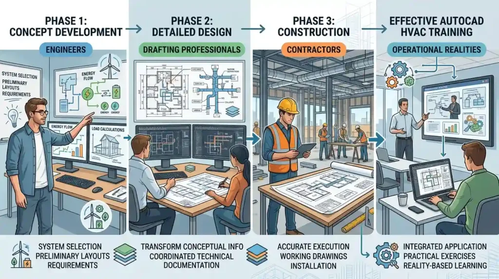
During concept development, engineers focus on system selection, load requirements, and preliminary layouts.
During detailed design, drafting professionals transform conceptual information into coordinated technical documentation.
During construction, contractors rely on working drawings to execute installations accurately.
Effective AutoCAD HVAC training reflects these operational realities rather than treating drawings as isolated technical exercises.
How does AutoCAD HVAC training teach schematic drawing development?
AutoCAD HVAC training teaches schematic drawing development by focusing on system relationships, airflow paths, equipment connectivity, control logic, and engineering communication standards before introducing detailed construction documentation requirements or installation-specific information.
Schematic drawing instruction generally begins with system understanding rather than software complexity.
Learners study key HVAC entities including:
- Air Handling Units (AHUs)
- Fan Coil Units (FCUs)
- Chillers
- Cooling towers
- Duct systems
- Pipe networks
- Control systems
- Diffusers and grilles
The training objective is to help learners visualise system operation.
For example, a schematic chilled water system illustrates how water circulates between chillers, pumps, air handling units, and return lines. The drawing prioritises functionality rather than exact physical location.
AutoCAD exercises at this stage often include:
- Symbol creation
- Block management
- Layer organisation
- Flow direction representation
- Equipment identification
- System connectivity mapping
These exercises develop technical communication skills. Stakeholders can quickly understand system intent without reviewing detailed installation drawings.
What competencies are developed through schematic drawing exercises?
Schematic-focused training strengthens:
- System thinking
- Design interpretation
- Engineering communication
- Conceptual planning
- Equipment relationship analysis
- Workflow visualisation
These competencies support collaboration between engineers, project managers, estimators, and facility stakeholders.
How does training transition from schematic drawings to working drawings?

Training transitions from schematic drawings to working drawings by converting conceptual system layouts into coordinated technical documents containing dimensions, specifications, installation details, schedules, annotations, and construction-level information required for project execution.
This transition represents one of the most important learning milestones in HVAC design education.
Many learners can create a schematic layout. Fewer can develop a complete working drawing package suitable for construction teams.
Training typically introduces additional requirements such as:
- Scale accuracy
- Space coordination
- Equipment clearances
- Duct sizing
- Pipe routing
- Elevation references
- Section drawings
- Detail callouts
Each requirement adds practical complexity.
For example, a schematic duct connection simply shows airflow movement between equipment and spaces.
A working drawing must specify:
- Duct dimensions
- Material specifications
- Fittings
- Supports
- Insulation requirements
- Installation locations
The shift requires both software proficiency and engineering understanding.
Why is this transition important for workplace performance?
Many organisations measure project success through:
- Installation accuracy
- Reduced rework
- Coordination efficiency
- Construction productivity
- Compliance performance
Employees who understand the relationship between schematic and working drawings contribute more effectively across these performance indicators.
This capability improves collaboration between design teams and field personnel.
What distinguishes a working drawing from a schematic drawing in AutoCAD workflows?
A working drawing differs from a schematic drawing because it contains precise technical information necessary for construction, whereas a schematic drawing focuses on system representation, operational relationships, and engineering communication without installation-level detail.
The distinction becomes clearer when comparing their functional characteristics.
| Attribute | Schematic Drawing | Working Drawing |
|---|---|---|
| Primary Purpose | System understanding | Construction execution |
| Detail Level | Conceptual | Technical |
| Dimensions | Limited | Comprehensive |
| Installation Information | Minimal | Extensive |
| Equipment Location Accuracy | Approximate | Precise |
| Coordination Requirements | Basic | High |
| Contractor Usage | Reference | Primary document |
| Procurement Support | Limited | Essential |
This comparison illustrates why both drawing types remain essential throughout HVAC project delivery.
Neither replaces the other.
One supports engineering communication.
The other supports physical implementation.
How do project-based training methods improve understanding of both drawing types?
Project-based training improves understanding by allowing learners to create schematic drawings, refine designs, coordinate building systems, and ultimately produce working drawings that reflect real-world project documentation requirements and workflow expectations.
Corporate learning environments increasingly favour project-based methodologies because they mirror workplace processes.
Rather than completing isolated drafting exercises, learners progress through realistic project scenarios.
A typical workflow includes:
- Reviewing building requirements.
- Developing HVAC system concepts.
- Producing schematic layouts.
- Performing coordination reviews.
- Creating detailed working drawings.
- Generating schedules and documentation.
This sequence reinforces the relationship between conceptual design and implementation.
Learning retention improves when participants experience the complete workflow rather than individual drafting tasks.
Why do organisations favour project-based technical training?
Workplace performance depends on applied competence rather than theoretical knowledge alone.
Project-based learning helps organisations assess:
- Technical accuracy
- Documentation quality
- Process understanding
- Coordination capability
- Problem-solving skills
These competencies directly influence project outcomes.
How do schematic and working drawing skills support business performance?
Schematic and working drawing skills support business performance by improving communication, reducing design errors, enhancing coordination, accelerating project delivery, and creating documentation standards that support operational efficiency throughout project execution.
Technical documentation quality has measurable business implications.
Poor schematic communication often leads to misunderstanding during design reviews.
Poor working drawings frequently result in installation errors, delays, and costly rework.
Industry studies regularly identify coordination failures as a major source of construction inefficiency.
Training that develops competency in both drawing categories addresses this challenge.
Key organisational benefits
Organisations benefit through:
- Improved design consistency
- Reduced documentation errors
- Better contractor coordination
- Faster project approvals
- Stronger compliance outcomes
- Improved asset management records
These outcomes support both operational performance and strategic workforce development objectives.
Workforce capability and skill-gap reduction
Many organisations identify technical documentation capability as a critical engineering skill gap.
Structured HVAC training addresses deficiencies in:
- Drafting standards
- Design interpretation
- Construction documentation
- System coordination
- Technical communication
This supports succession planning and workforce readiness initiatives.
How should HR teams evaluate HVAC training that covers drawing development?
HR teams should evaluate HVAC training through learning outcomes, project-based assessment methods, software competency development, documentation standards coverage, workplace applicability, and measurable performance improvements aligned with organisational objectives.
Training evaluation requires more than reviewing course titles.
Decision-makers should assess whether a programme develops practical competencies across the entire HVAC documentation process.
Key evaluation criteria include:
Technical coverage
The programme should address:
- HVAC system fundamentals
- Schematic development
- Working drawing production
- AutoCAD workflows
- Documentation standards
Practical application
Learners should complete realistic projects rather than isolated software exercises.
Practical application demonstrates skill transfer potential.
Assessment methodology
Effective programmes assess:
- Design interpretation
- Drawing accuracy
- Documentation quality
- Coordination capability
Assessment evidence provides stronger indicators of workplace readiness.
Business relevance
Training should support organisational objectives including:
- Productivity improvement
- Error reduction
- Workforce development
- Technical capability enhancement
The strongest programmes connect learning outcomes to operational performance indicators.
What learning path best develops competency in HVAC drawing documentation?
The most effective learning path progresses from HVAC system understanding to schematic development, AutoCAD proficiency, working drawing production, project coordination, and practical documentation exercises that replicate professional engineering environments and business requirements.
Skill development follows a structured sequence.
Learners first understand HVAC systems.
They then learn how systems are represented schematically.
Next comes software application.
After that, training focuses on technical documentation and coordination.
This progression reflects professional practice.
Skipping foundational stages often creates competency gaps later in the learning process.
The AutoCAD HVAC and Plumbing Design Training Course follows this type of structured development model by combining HVAC design principles with practical drafting workflows and documentation requirements.
Discover More from Our Guide Library:
How Are Sections and Construction Details Produced in AutoCAD HVAC Training?
How Does AutoCAD HVAC Training Prepare Engineers for Multi-Discipline Collaboration?
From an organisational perspective, this learning path produces professionals who understand both the engineering logic behind a design and the technical documentation required to implement it successfully.
The distinction between schematic and working drawings, therefore, becomes more than a drafting topic. It becomes a core competency that supports project communication, construction accuracy, workforce capability development, and measurable business performance outcomes.
Frequently Asked Questions
What skills are taught in an AutoCAD HVAC and Plumbing Design Training Course?
The AutoCAD HVAC and Plumbing Design Training Course covers HVAC system layouts, plumbing design principles, schematic drawings, working drawings, ductwork design, piping systems, and AutoCAD drafting techniques. Imperial Corporate Training Institute focuses on developing practical design and technical documentation skills used in building services projects.
Does an AutoCAD HVAC and Plumbing Design Training Course include both HVAC and plumbing systems?
Yes, the AutoCAD HVAC and Plumbing Design Training Course typically covers both HVAC and plumbing design workflows. At Imperial Corporate Training Institute, learners study system layouts, equipment placement, piping networks, duct routing, and construction documentation standards.
Why is learning HVAC and plumbing design in AutoCAD important?
AutoCAD is widely used for creating accurate HVAC and plumbing drawings in commercial, residential, and industrial projects. The AutoCAD HVAC and Plumbing Design Training Course helps learners develop drafting, coordination, and technical documentation skills required for engineering and construction environments.
What is the difference between schematic and working drawings in HVAC design?
Schematic drawings show system concepts, equipment relationships, and flow paths, while working drawings provide detailed dimensions and installation information. The AutoCAD HVAC and Plumbing Design Training Course at Imperial Corporate Training Institute helps learners understand how both drawing types support different project stages.