
HVAC projects depend on accurate technical documentation. Every stage of design, coordination, construction, and maintenance relies on drawings that communicate information clearly between engineers, designers, contractors, project managers, and facility teams. Two of the most important drawing categories are schematic HVAC drawings and installation HVAC drawings. Understanding the difference between them improves project coordination, reduces rework, and strengthens technical capability across engineering and construction teams.
For organisations involved in building services, facilities management, construction, manufacturing, healthcare, education, and commercial property development, the ability to interpret HVAC drawings directly influences project performance indicators such as installation accuracy, construction timelines, cost control, and compliance outcomes.
Schematic vs Installation HVAC Drawings
Schematic HVAC drawings explain system functionality and airflow relationships, while installation HVAC drawings provide the precise dimensions, locations, specifications, and construction details required for physical installation. One supports conceptual understanding. The other supports execution and construction activities.
Both drawing types serve different business and technical objectives. A schematic drawing focuses on how an HVAC system operates. It shows the relationship between equipment, ducts, pipes, controls, and airflow paths without emphasising exact physical placement.
An installation drawing, often called a working drawing, translates the design into construction-ready information. It includes dimensions, elevations, duct sizes, equipment locations, annotations, and installation requirements.
In corporate environments, schematic drawings support design reviews, stakeholder communication, and engineering coordination. Installation drawings support procurement, site execution, quality control, and commissioning activities.
The distinction becomes critical in large projects where multiple disciplines, including mechanical, electrical, plumbing, fire protection, and architectural teams, must collaborate effectively.
Why Do Organisations Use Schematic HVAC Drawings During Project Planning?
Schematic HVAC drawings allow project teams to visualise system operation, evaluate design concepts, coordinate engineering decisions, and identify functional requirements before detailed construction documentation begins.

During the early design phase, organisations focus on system performance rather than physical installation details.
A schematic drawing typically illustrates:
- Air handling units
- Chillers
- Boilers
- Pumps
- Fans
- Ductwork routes
- Pipe networks
- Control systems
- Airflow directions
These drawings simplify complex systems into understandable diagrams.
Engineering managers use schematic drawings to review capacity requirements. Facilities teams use them to validate operational objectives. Project stakeholders use them to understand system interactions without requiring advanced technical knowledge.
Industries such as healthcare, manufacturing, data centres, and commercial real estate frequently use schematic diagrams during concept development because these projects involve extensive HVAC infrastructure and strict performance requirements.
How Do Installation HVAC Drawings Support Construction Activities?
Installation HVAC drawings provide the exact information required for fabrication, procurement, installation, inspection, testing, and commissioning activities across the construction lifecycle.
Construction teams require precise instructions.
Installation drawings include:
- Exact equipment locations
- Duct dimensions
- Pipe sizes
- Elevation details
- Section views
- Material specifications
- Connection details
- Support requirements
- Coordination references
Unlike schematic drawings, installation drawings reflect physical reality.
Mechanical contractors rely on these drawings to fabricate ductwork and piping systems. Procurement teams use them to source equipment. Quality inspectors use them to verify compliance against project specifications.
A coordinated installation drawing reduces clashes between HVAC systems and other building services. This directly impacts project KPIs such as schedule adherence, labour productivity, and rework reduction.
How Does the HVAC Drawing Process Work in Corporate Projects?
HVAC documentation progresses through structured stages including conceptual design, schematic development, detailed engineering, installation documentation, construction support, and commissioning verification.
Concept Development
Engineers identify building requirements.
Examples include:
- Cooling loads
- Heating demands
- Ventilation rates
- Indoor air quality targets
- Energy efficiency objectives
The output is a preliminary system concept.
Schematic Design
Engineers create simplified system diagrams.
These diagrams define system relationships and operational logic.
Decision-makers evaluate feasibility, budget alignment, and performance requirements during this stage.
Detailed Design
Engineers calculate airflow rates, pressure losses, equipment capacities, and system performance characteristics.
Technical specifications become more detailed.
Installation Documentation
Design information converts into construction-ready drawings.
All dimensions, coordinates, elevations, and component specifications are finalised.
Construction and Verification
Installation teams execute the work.
Quality assurance teams compare completed installations against approved drawings before commissioning activities begin.
This structured process creates consistency across multidisciplinary projects.
What Components Are Included in Schematic HVAC Drawings?
Schematic HVAC drawings contain simplified representations of equipment, airflow paths, control relationships, piping systems, and operational sequences without construction-level dimensions or installation details.
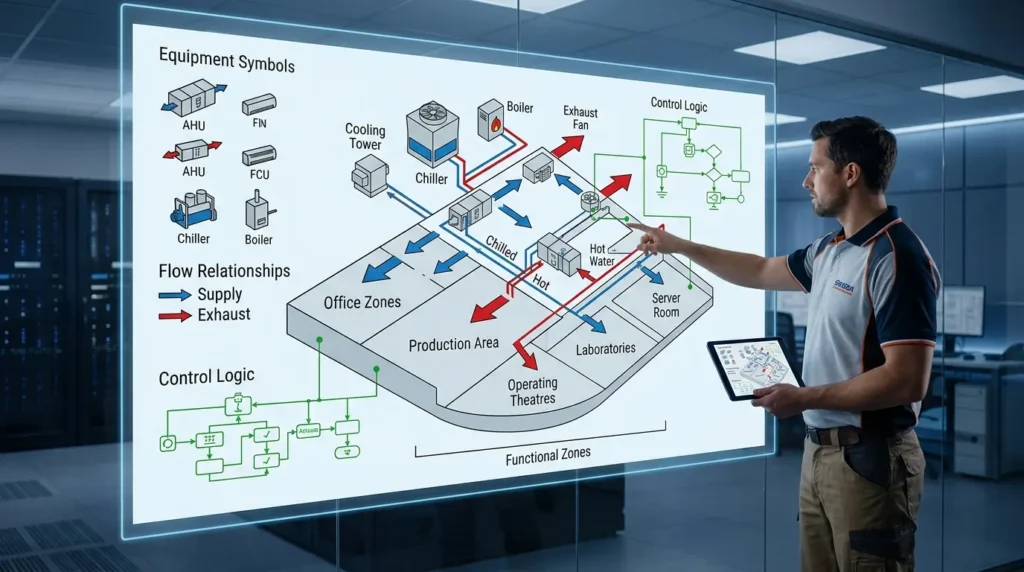
Equipment Symbols
Equipment symbols represent system components.
Examples include:
- Air handling units
- Fan coil units
- Cooling towers
- Chillers
- Boilers
- Exhaust fans
These symbols help stakeholders understand system configuration quickly.
Flow Relationships
Schematic drawings identify airflow and water flow paths.
Directional arrows show how energy and air move throughout the building.
Control Logic
Control relationships illustrate how components interact.
This information supports commissioning planning and building management system integration.
Functional Zones
Many schematic drawings divide buildings into functional areas.
Examples include office zones, production areas, operating theatres, laboratories, and server rooms.
This approach improves operational understanding.
What Components Are Included in Installation HVAC Drawings?
Installation HVAC drawings contain dimensions, elevations, duct layouts, pipe routing, equipment placement, schedules, sections, and construction specifications required for physical installation.
Plan Views
Plan views show equipment and services from a top-down perspective.
They define exact placement within building layouts.
Sections and Elevations
Section drawings reveal vertical relationships.
They help installers understand ceiling spaces, risers, and service coordination requirements.
Equipment Schedules
Schedules provide technical specifications.
Typical information includes:
- Capacity
- Airflow rates
- Power requirements
- Manufacturer references
- Performance criteria
Coordination Details
Installation drawings identify interactions with architectural, structural, and electrical systems.
This reduces clashes and installation conflicts.
Construction Notes
Construction notes communicate installation standards and project-specific requirements.
These notes support quality assurance processes.
How Do Organisations Train Employees to Read Both Drawing Types?
Organisations develop HVAC drawing competency through structured learning programmes that combine technical theory, software training, practical exercises, simulations, and performance assessments.
Employee skill gaps frequently emerge when technicians understand installation activities but struggle to interpret design intent.
Training programmes address these gaps through progressive learning pathways.
Common delivery formats include:
- Classroom workshops
- Virtual instructor-led training
- Self-paced online modules
- Hybrid learning programmes
- Project-based assignments
Learning methodologies typically include:
- Case-based learning
- Technical simulations
- Drawing interpretation exercises
- Collaborative workshops
- Practical assessments
Engineering organisations often establish competency frameworks with measurable milestones.
Examples include:
- Drawing interpretation accuracy
- Coordination review performance
- Clash detection capability
- Installation compliance rates
When discussing technical development pathways, readers often move towards evaluating how structured software-based learning supports drawing interpretation.
This is an appropriate point to reference an article explaining:
For deeper insight, enrol in:
AutoCAD HVAC and Plumbing Design Training Course
What Business Benefits Result from Understanding Both Drawing Types?
Accurate interpretation of schematic and installation drawings improves project efficiency, reduces construction errors, enhances communication, strengthens quality control, and supports predictable project delivery.
Organisations measure performance through operational KPIs.
HVAC drawing competency contributes directly to several metrics.
Reduced Rework
Construction rework creates schedule delays and budget overruns.
Teams that understand drawing intent identify issues earlier.
Improved Coordination
Large projects involve multiple disciplines.
Drawing literacy improves communication between mechanical, electrical, plumbing, and architectural teams.
Faster Project Delivery
Accurate interpretation reduces installation delays.
Project managers gain better control over timelines.
Better Quality Outcomes
Installations align more closely with engineering specifications.
Quality inspections identify fewer non-conformities.
Stronger Knowledge Transfer
Technical documentation becomes easier to communicate across departments.
This supports workforce continuity and succession planning.
Which Industries Depend Most on Schematic and Installation HVAC Drawings?
Industries with complex building services systems rely heavily on both drawing types to support compliance, operational performance, safety requirements, and asset management objectives.
Healthcare
Hospitals require strict airflow control.
Operating theatres, isolation rooms, and laboratories depend on accurate HVAC documentation.
Manufacturing
Production facilities require temperature and environmental control.
HVAC drawings support operational consistency.
Data Centres
Cooling systems protect critical infrastructure.
Detailed installation documentation reduces operational risk.
Commercial Real Estate
Office towers, shopping centres, and mixed-use developments rely on coordinated HVAC systems.
Education
Universities and schools require efficient environmental control across diverse building types.
Each industry uses schematic drawings for planning and installation drawings for execution.
What Common Misconceptions Exist About HVAC Drawings?
Many organisations incorrectly assume schematic and installation drawings are interchangeable, resulting in communication errors, training gaps, coordination failures, and reduced project efficiency.
Misconception 1: Schematic Drawings Are Construction Documents
Schematic drawings explain concepts.
They do not provide sufficient information for installation activities.
Misconception 2: Installation Drawings Explain System Logic
Installation drawings focus on execution.
They do not always communicate operational relationships clearly.
Misconception 3: Software Knowledge Equals Drawing Competence
Technical software proficiency differs from engineering understanding.
An employee can operate design software without interpreting system intent effectively.
Misconception 4: Drawing Interpretation Requires Only Engineers
Project managers, supervisors, procurement teams, commissioning specialists, and facility managers all benefit from drawing literacy.
Misconception 5: Drawing Training Produces No Measurable ROI
Organisations track measurable outcomes including reduced errors, improved productivity, lower rework costs, and faster project delivery.
How Do Schematic and Installation Drawings Contribute to Organisational Performance?
Together, schematic and installation drawings create a complete information framework that supports planning, execution, quality assurance, operational readiness, and long-term asset management.
Schematic drawings communicate system intent.
Installation drawings communicate implementation requirements.
Discover More from Our Guide Library:
How Does AutoCAD Handle Sections and Details for HVAC System Drawings?
What Is the Role of the HVAC Designer in a Multi-Discipline Design Team?
When employees understand both, organisations achieve stronger collaboration, more efficient project execution, and improved technical consistency.
From a workforce development perspective, drawing literacy represents a practical technical competency. It supports engineering accuracy, construction quality, operational reliability, and knowledge transfer across teams. As organisations invest in technical training, the ability to interpret both schematic and installation HVAC drawings becomes an essential capability for managing increasingly complex building services projects.
Frequently Asked Questions
Who should attend an AutoCAD HVAC and Plumbing Design Training Course?
This course is suitable for mechanical engineers, HVAC technicians, plumbing designers, CAD operators, project engineers, and construction professionals. Imperial Corporate Training Institute structures the training to support both new learners and experienced professionals working with building services drawings.
Why is AutoCAD important for HVAC and plumbing design?
AutoCAD helps professionals create accurate HVAC and plumbing drawings that support design coordination, installation planning, and project documentation. It improves drafting efficiency and reduces errors during construction and facility development projects.
What skills can participants gain from an AutoCAD HVAC and Plumbing Design Training Course?
Participants learn HVAC drafting, plumbing system design, duct and pipe routing, drawing interpretation, layer management, and technical documentation. The AutoCAD HVAC and Plumbing Design Training Course at Imperial Corporate Training Institute also develops practical skills for producing industry-standard engineering drawings.
How does AutoCAD support HVAC and plumbing project coordination?
AutoCAD enables engineers and designers to create detailed layouts that integrate HVAC, plumbing, electrical, and architectural systems. This improves multidisciplinary coordination, minimises clashes, and supports efficient project delivery across commercial and industrial developments.