
Chiller plant systems define the operational efficiency of commercial buildings, hospitals, industrial facilities, airports, and data centres. Mechanical engineers, HVAC designers, and technical drafting teams rely on structured drawing production methods to coordinate chilled water systems, cooling towers, pumps, piping layouts, and control integration. Training programmes focused on AutoCAD HVAC workflows increasingly prioritise drawing production because organisations need professionals who can deliver coordinated documentation rather than isolated drafting tasks.
Understanding how training programmes teach chiller plant drawing development helps HR teams, engineering managers, and technical learners evaluate whether a learning approach supports real operational requirements. Many organisations assess HVAC training based on measurable drafting outcomes, multidisciplinary coordination capability, and readiness for live project environments.
Why does chiller plant drawing production require structured AutoCAD HVAC training?
Chiller plant drawing production requires structured AutoCAD HVAC training because engineers must coordinate equipment layouts, piping systems, hydraulic calculations, annotation standards, and multidisciplinary documentation into a single workflow that supports construction, maintenance, commissioning, and operational efficiency within commercial building environments.
Chiller plant systems involve interconnected mechanical components. Drawings must communicate exact technical relationships between chillers, pumps, cooling towers, valves, pipe routes, expansion tanks, and control systems. Poorly coordinated documentation increases installation errors, delays commissioning, and creates operational inefficiencies.
Training programmes focused on HVAC drafting therefore teach drawing production as a process rather than a software exercise. Learners study how project information flows from concept layouts to construction-ready documentation.
In corporate engineering environments, HVAC drawing production often follows layered documentation stages. These stages include:
- Schematic design
- Equipment arrangement layouts
- Plant room coordination
- Pipe routing development
- Section detailing
- Isometric drafting
- Annotation and tagging
- Construction documentation
- Revision management
The educational foundation for these workflows often begins with conceptual system understanding. Readers comparing drafting methodologies often review educational resources explaining system behaviour before evaluating detailed production workflows.
Articles discussing:
How Does AutoCAD HVAC Handle Chiller Plant and Cooling Tower System Design? provide awareness-stage context regarding HVAC system coordination principles before moving into detailed drawing production evaluation.
Training effectiveness depends on whether learners understand system logic alongside drafting execution. Organisations increasingly measure technical training performance through operational KPIs such as drawing accuracy, coordination conflict reduction, and project turnaround time.
Engineering firms also evaluate drafting staff according to documentation consistency. Standardised training reduces variation between team members. This improves project delivery speed and decreases quality-control revisions.
How are chiller plant layouts introduced during AutoCAD HVAC training?
Chiller plant layouts are introduced through equipment placement logic, circulation flow planning, spatial coordination exercises, and plant room arrangement standards that replicate real engineering documentation practices used in commercial construction and industrial HVAC environments across multidisciplinary project teams.
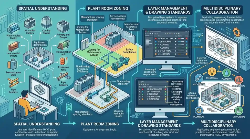
The first stage of chiller plant drafting focuses on spatial understanding. Learners study how physical equipment interacts within plant room constraints.
Training programmes usually begin with:
Equipment Identification
Learners identify major HVAC plant components, including:
- Water-cooled chillers
- Air-cooled chillers
- Cooling towers
- Primary pumps
- Secondary pumps
- Heat exchangers
- Pressurisation units
- Expansion tanks
- Pipe headers
- Isolation valves
Understanding equipment function supports accurate drafting decisions.
Plant Room Zoning
Training then moves into equipment arrangement logic. Engineers learn how plant rooms are divided into operational zones to improve maintenance access, pipe routing efficiency, and safety compliance.
For example, chillers require maintenance clearance zones. Pump arrangements require alignment considerations. Cooling tower pipe routes must minimise hydraulic losses.
Training exercises often replicate real project conditions where learners position equipment according to:
- Manufacturer spacing standards
- Service access requirements
- Pipe routing efficiency
- Structural coordination
- Mechanical airflow requirements
This process teaches workflow thinking rather than isolated drafting commands.
Layer Management and Drawing Standards
AutoCAD HVAC training also introduces drawing organisation standards. Large engineering firms use disciplined layer systems to separate mechanical, plumbing, electrical, and structural elements.
Learners therefore practise:
- Layer naming conventions
- Colour standards
- Lineweight control
- Annotation scaling
- Block management
- External reference coordination
These workflows support multidisciplinary collaboration.
Many technical teams evaluating structured drafting development explore the:
AutoCAD HVAC and Plumbing Design Training Course because it focuses on coordinated mechanical documentation methods used in operational project environments.
How do training programmes teach chilled water piping documentation?
Training programmes teach chilled water piping documentation through progressive routing exercises, hydraulic flow coordination, pipe sizing interpretation, fitting placement standards, and construction drawing practices that align mechanical drafting with installation sequencing and operational plant efficiency requirements.
Piping systems define the functional structure of chiller plants. Poor pipe coordination creates clashes, pressure losses, and installation inefficiencies.
Training programmes therefore dedicate significant time to piping workflows.
Routing Methodology
Learners begin with schematic piping diagrams. These simplified drawings establish flow direction and equipment relationships.
After schematic development, trainees convert conceptual diagrams into coordinated layouts using AutoCAD HVAC tools.
Key routing concepts include:
- Primary-secondary piping systems
- Reverse return systems
- Variable flow arrangements
- Header configuration
- Bypass arrangements
- Isolation strategies
The objective is operational clarity.
Pipe Sizing Interpretation
Training programmes also introduce engineering documentation interpretation. Drafting teams regularly coordinate with mechanical calculations prepared by design engineers.
Learners study:
- Pipe sizing schedules
- Flow rates
- Velocity criteria
- Pressure drop requirements
- Valve selection references
This improves communication between design and drafting departments.
Isometric Drawing Production
Advanced training frequently includes isometric drafting exercises. Isometric drawings help fabrication and installation teams visualise pipe geometry.
These exercises improve understanding of:
- Elevation transitions
- Pipe offsets
- Fitting orientation
- Connection sequencing
- Fabrication documentation
Organisations benefit because isometric competency reduces field interpretation errors.
Annotation Standards
Technical annotation forms a major component of piping documentation.
Training therefore covers:
- Pipe tagging
- Flow direction indicators
- Valve numbering
- Equipment schedules
- Line identification systems
- Revision clouds
Consistent annotation improves commissioning and maintenance efficiency.
Engineering managers often evaluate drafting programmes according to how effectively they prepare learners for coordinated construction documentation rather than isolated CAD operation.
How are cooling tower systems detailed within HVAC drafting workflows?
Cooling tower systems are detailed through condenser water routing exercises, elevation coordination methods, structural placement studies, and equipment connectivity documentation that teach learners how external plant systems integrate with internal chilled water infrastructure within commercial HVAC projects.
Cooling tower documentation differs from internal mechanical room drafting because it involves external infrastructure coordination.
Training programmes therefore address environmental and structural considerations.
External Equipment Coordination
Cooling towers interact with:
- Roof structures
- Steel supports
- Drainage systems
- Electrical feeds
- Access platforms
- Water treatment systems
Learners study how these interfaces influence drawing production.
Elevation and Section Development
Two-dimensional plans alone do not fully communicate cooling tower systems. Training therefore includes:
- Section views
- Elevation drawings
- Pipe support detailing
- Platform coordination
These drawing types help installation teams understand vertical relationships.
Condenser Water Routing
Condenser water systems require careful pipe routing to maintain hydraulic performance.
Training exercises frequently include:
- Pipe slope coordination
- Expansion accommodation
- Vibration isolation detailing
- Thermal movement considerations
These workflows improve practical engineering awareness.
Coordination with Other Disciplines
Cooling tower systems involve multidisciplinary coordination. Training therefore introduces collaboration principles involving:
- Structural engineers
- Electrical engineers
- Plumbing teams
- Fire protection consultants
Corporate training programmes increasingly prioritise interdisciplinary communication because coordination failures significantly increase project costs.
How does AutoCAD HVAC training replicate real project documentation workflows?
AutoCAD HVAC training replicates real project documentation workflows by using phased drawing exercises, revision tracking systems, coordinated sheet production, and construction-document standards that mirror the operational structure used by engineering consultancies and MEP contracting organisations.
Modern HVAC drafting training increasingly follows project simulation models rather than software tutorials.
This shift reflects industry demand for operational readiness.
Phased Documentation Exercises
Learners frequently progress through structured project stages:
| Project Phase | Drafting Activity | Operational Objective |
|---|---|---|
| Concept Design | Schematic layouts | System understanding |
| Design Development | Equipment coordination | Space planning |
| Construction Documentation | Detailed drawings | Installation support |
| Revision Stage | Mark-up integration | Quality control |
| Final Submission | Sheet compilation | Project delivery |
This workflow improves project literacy.
Sheet Set Coordination
Engineering projects contain multiple interconnected sheets. Training programmes therefore teach:
- Drawing indexing
- Sheet referencing
- View coordination
- Detail referencing
- Revision numbering
These standards improve documentation consistency.
Revision Management
Real projects undergo continuous updates. Drafting professionals therefore require revision management skills.
Training programmes replicate this process using:
- Redline mark-ups
- Version tracking
- Cloud revisions
- Consultant comments
- Coordination updates
These exercises improve workplace readiness.
Collaborative Workflow Simulation
Some programmes also simulate collaborative production environments where learners coordinate mechanical layouts with architectural and structural drawings.
This reflects real industry practice because HVAC documentation rarely exists independently.
What technical detailing skills are prioritised during chiller plant drafting instruction?
Chiller plant drafting instruction prioritises technical detailing skills that improve installation clarity, operational maintainability, spatial coordination, and documentation precision within complex HVAC infrastructure environments involving multiple engineering systems and stakeholder requirements.

Technical detailing determines whether a drawing functions effectively on-site.
Training therefore focuses heavily on documentation clarity.
Equipment Connection Detailing
Learners study how to detail:
- Flanged connections
- Flexible connectors
- Valve arrangements
- Instrumentation locations
- Drain systems
- Venting provisions
These details support installation sequencing.
Section and Callout Production
Complex plant rooms require enlarged detail views.
Training includes:
- Section creation
- Detail callouts
- Enlarged mechanical layouts
- Component identification
These workflows improve communication between engineers and site teams.
Coordination Detailing
Clash prevention forms a major drafting objective.
Training therefore addresses:
- Ceiling coordination
- Structural beam avoidance
- Pipe elevation planning
- Access route preservation
Coordination competency improves project delivery efficiency.
Standards Compliance
HVAC drafting must align with:
- Mechanical engineering standards
- Local building regulations
- Corporate CAD standards
- Documentation protocols
Training programmes introduce these frameworks to improve professional readiness.
How do organisations evaluate the effectiveness of AutoCAD HVAC training for chiller plant drafting?
Organisations evaluate AutoCAD HVAC training effectiveness through measurable drafting accuracy, coordination capability, project delivery efficiency, documentation consistency, and workforce readiness metrics that align technical learning outcomes with operational engineering performance requirements.
Corporate learning decisions increasingly depend on measurable business outcomes.
Training evaluation therefore extends beyond software familiarity.
Workforce Readiness Metrics
Engineering organisations commonly assess:
- Drawing accuracy rates
- Coordination error frequency
- Revision reduction
- Project turnaround time
- Documentation completeness
These metrics connect training with operational efficiency.
Learning Delivery Models
Different organisations use different delivery structures.
Common training formats include:
| Delivery Model | Operational Use Case | Business Benefit |
|---|---|---|
| Instructor-led classroom | Graduate engineering teams | Structured onboarding |
| Corporate workshops | Internal upskilling | Workflow standardisation |
| Project-based learning | Design departments | Practical application |
| Hybrid technical training | Distributed teams | Flexible learning access |
HR departments evaluate which model supports workforce structure and operational timelines.
Skill Gap Reduction
Technical drafting gaps frequently appear in:
- Plant room coordination
- Piping documentation
- Multidisciplinary collaboration
- Revision management
- Construction detailing
Structured training reduces these competency gaps systematically.
Performance-Based Learning
Many organisations now evaluate HVAC training according to project performance indicators rather than attendance completion.
Relevant KPIs include:
- Reduced RFIs
- Lower rework frequency
- Faster drawing approval
- Improved installation coordination
- Reduced construction clashes
These metrics align learning investment with business performance.
When organisations move from educational evaluation toward implementation readiness, decision-stage resources discussing whether:
Does Imperial’s HVAC Course Cover Chiller System Drawing Production? often become relevant because stakeholders begin comparing programme coverage against operational drafting requirements.
How does practical HVAC drafting training support long-term engineering capability?
Practical HVAC drafting training supports long-term engineering capability by developing procedural consistency, multidisciplinary coordination awareness, documentation accuracy, and operational communication skills that improve project execution quality across mechanical engineering and building services environments.
Technical drawing production influences every stage of HVAC project delivery.
Accurate documentation improves:
- Procurement coordination
- Installation sequencing
- Site communication
- Commissioning efficiency
- Maintenance planning
Training programmes that replicate operational drafting workflows therefore create broader engineering value beyond software proficiency.
Engineering Communication
Drawings function as communication systems between:
- Mechanical engineers
- Contractors
- Procurement teams
- Facility managers
- Commissioning specialists
Training improves technical communication precision.
Standardisation Across Teams
Organisations increasingly standardise drafting workflows to improve scalability.
Structured training supports:
- Uniform documentation methods
- Shared CAD standards
- Reduced coordination conflicts
- Faster onboarding
These outcomes improve operational consistency.
Integration with Broader Building Services Training
Chiller plant drafting also intersects with:
- Plumbing coordination
- Fire protection systems
- Electrical services
- Building management systems
Training programmes that include integrated workflows better reflect real engineering environments.
Discover More from Our Guide Library:
What Is the Long-Term Career Value of AutoCAD HVAC Certification for MEP Engineers?
What Symbol Libraries and Standard Blocks Are Used in AutoCAD HVAC Drafting?
Long-Term Professional Development
HVAC drafting competency supports progression into:
- MEP coordination
- BIM modelling
- Project engineering
- Technical supervision
- Mechanical design management
This explains why many organisations evaluate training programmes according to long-term capability development rather than short-term software instruction alone.
How does AutoCAD HVAC training improve mechanical drafting skills?
AutoCAD HVAC training improves technical drafting accuracy, equipment layout planning, pipe routing, and HVAC system documentation. The AutoCAD HVAC and Plumbing Design Training Course also develops coordination skills required for multidisciplinary construction and engineering projects.
Does the AutoCAD HVAC and Plumbing Design Training Course include chiller plant drawing production?
Yes, the AutoCAD HVAC and Plumbing Design Training Course includes chiller plant layouts, piping documentation, cooling tower coordination, and mechanical room detailing. Imperial Corporate Training Institute focuses on practical HVAC drafting workflows aligned with industry documentation standards.
Why is AutoCAD HVAC training important for MEP projects?
AutoCAD HVAC training supports accurate HVAC design documentation, clash reduction, and coordinated mechanical system planning in MEP projects. The AutoCAD HVAC and Plumbing Design Training Course helps professionals understand drafting standards used in commercial and industrial building environments.