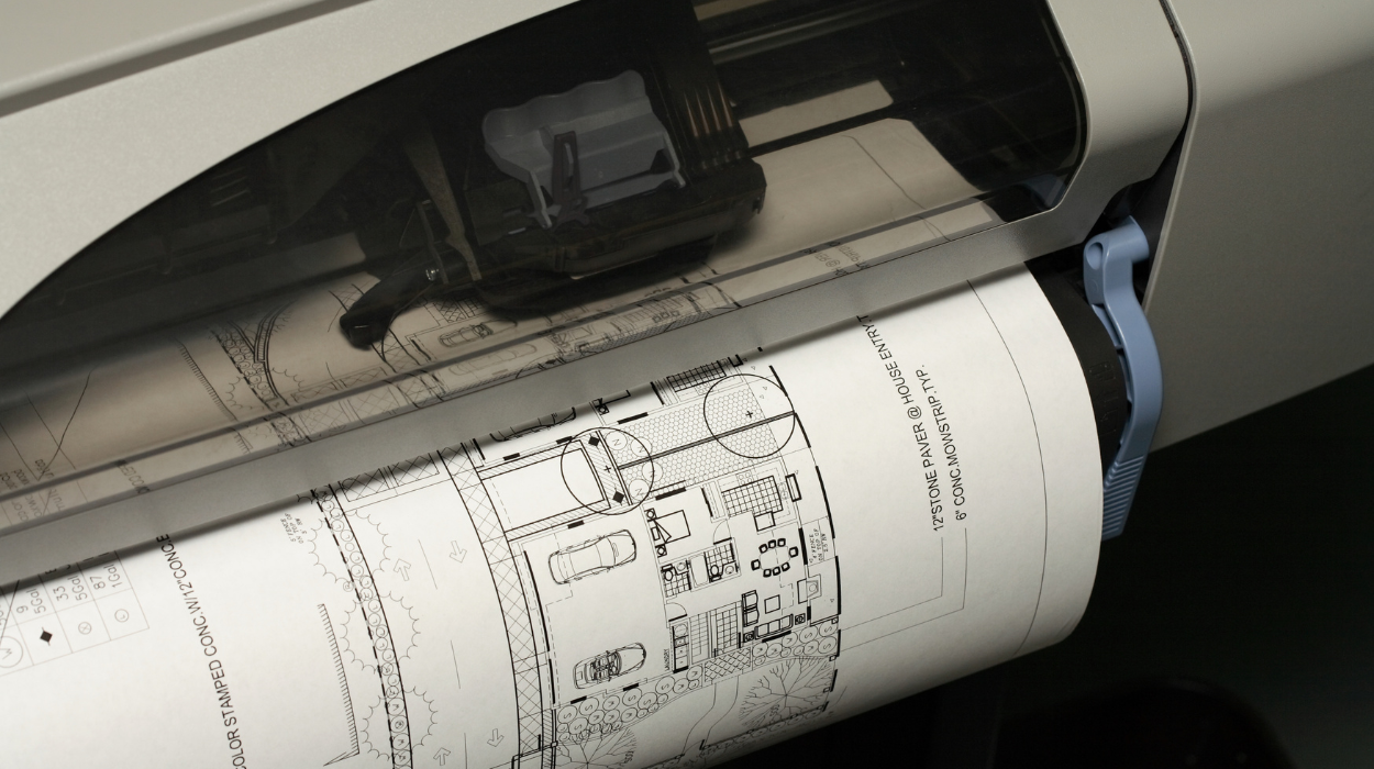
AutoCAD HVAC drawings form the technical communication framework used by engineers, designers, contractors, and facility teams during building projects. Printing and plotting HVAC drawings for issue is the controlled process of converting digital design files into standardised documents that can be reviewed, approved, constructed, and archived. In corporate environments, accurate drawing output supports project coordination, quality assurance, regulatory compliance, and operational efficiency.
For organisations managing construction, facilities, engineering consultancy, or design projects, drawing issue procedures directly influence project timelines, rework rates, and communication accuracy. A structured plotting process ensures that stakeholders receive consistent documentation with the correct scale, title blocks, revisions, and plotting standards. This reduces errors, supports collaboration across departments, and improves project delivery performance.
What Is Printing and Plotting AutoCAD HVAC Drawings for Issue?
Printing and plotting AutoCAD HVAC drawings for issue is the process of converting HVAC design files into standardised, controlled documents with correct scales, layouts, revisions, and output settings so project teams can review, approve, construct, and maintain building systems accurately.
In HVAC design projects, digital drawings contain information about ductwork, air terminals, ventilation systems, chilled water piping, equipment schedules, and installation requirements. These drawings remain within the design environment until they are prepared for formal distribution.
Printing refers to producing physical copies on paper. Plotting refers to generating large-format engineering drawings using predefined output settings. In modern organisations, plotting also includes digital outputs such as PDF issue packages.
The process supports document control systems used in industries like construction, healthcare, manufacturing, education, and commercial real estate. Teams rely on issued drawings to coordinate installation activities, verify specifications, and maintain project records.
A controlled issue process improves communication between engineering departments, project managers, contractors, consultants, and facility operators.
Why Do Organisations Need Structured HVAC Drawing Issue Procedures?
Structured issue procedures ensure drawing consistency, reduce construction errors, support quality management systems, and improve coordination between departments, contractors, and stakeholders throughout the project lifecycle.
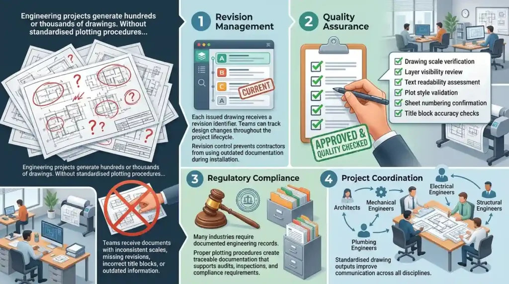
Engineering projects generate hundreds or thousands of drawings. Without standardised plotting procedures, teams receive documents with inconsistent scales, missing revisions, incorrect title blocks, or outdated information.
A structured process establishes clear rules for:
Revision Management
Each issued drawing receives a revision identifier. Teams can track design changes throughout the project lifecycle.
Revision control prevents contractors from using outdated documentation during installation.
Quality Assurance
Quality assurance procedures verify that drawings meet organisational standards before issue.
Checks include:
- Drawing scale verification
- Layer visibility review
- Text readability assessment
- Plot style validation
- Sheet numbering confirmation
- Title block accuracy checks
Regulatory Compliance
Many industries require documented engineering records.
Proper plotting procedures create traceable documentation that supports audits, inspections, and compliance requirements.
Project Coordination
Building projects involve multiple disciplines including architecture, mechanical engineering, electrical engineering, plumbing engineering, and structural engineering.
Standardised drawing outputs improve communication across all disciplines.
How Does the HVAC Drawing Plotting Process Work?
The HVAC plotting process follows a structured workflow that includes drawing preparation, layout configuration, scale verification, plot style assignment, output generation, quality review, approval, and document distribution.
Organisations typically implement a repeatable workflow to ensure consistency across projects.
Step 1: Prepare the HVAC Design Drawing
Design teams complete HVAC layouts, equipment schedules, duct routing, and system annotations.
Before plotting begins, designers verify that all design information is complete and current.
The drawing file becomes the source document for issue preparation.
Step 2: Configure Layouts
AutoCAD layouts define how the drawing will appear when printed.
Layouts contain:
- Title blocks
- Viewports
- Drawing scales
- Sheet references
- Project information
Multiple layouts can exist within a single drawing file.
Each layout serves a different documentation purpose.
Step 3: Assign Viewports and Scales
Viewports display model-space content within paper-space layouts.
Common HVAC scales include:
- 1:20
- 1:50
- 1:100
- 1:200
Scale selection depends on project requirements and drawing complexity.
Incorrect viewport scaling creates installation and coordination errors.
Step 4: Apply Plot Styles
Plot styles control how objects appear during output generation.
Plot styles define:
- Line weights
- Colours
- Line types
- Screening settings
Consistent plot styles improve readability and maintain organisational standards.
Step 5: Generate Output Files
The system generates output files according to project requirements.
Typical outputs include:
- PDF files
- A1 engineering drawings
- A0 construction packages
- Digital issue sets
Generated outputs enter the quality review stage.
Step 6: Perform Quality Control Reviews
Reviewers inspect drawings for technical and visual accuracy.
Checks focus on:
- Scale consistency
- Text clarity
- Sheet completeness
- Revision status
- Plot quality
Quality reviews reduce rework and document-related project delays.
Step 7: Approve and Issue Documentation
Approved drawings receive formal issue status.
Document control teams distribute issued files to relevant stakeholders.
The issue becomes part of the project’s official record.
What Components Are Included in HVAC Drawing Output Setup?
HVAC drawing output setup includes layouts, title blocks, viewports, plotting scales, plot styles, sheet sets, revision controls, file naming conventions, and document management standards.
Successful plotting depends on multiple interconnected components.
Layout Configuration
Layouts define the final appearance of engineering documentation.
Standardised layouts improve consistency across departments and projects.
Title Blocks
Title blocks contain essential project information.
Typical fields include:
- Project name
- Drawing title
- Drawing number
- Revision number
- Approval signatures
- Issue date
Title blocks support document traceability.
Plot Styles
Plot styles create visual consistency.
Engineering organisations often develop corporate plotting standards to ensure uniform documentation.
Sheet Set Management
Large projects contain multiple drawing sheets.
Sheet set management tools organise drawing collections and streamline output generation.
Revision Control Systems
Revision systems track document changes.
This ensures stakeholders always access current information.
Document Control Standards
Document control frameworks establish procedures for approval, storage, retrieval, and distribution.
These standards support organisational governance requirements.
How Is Plotting Layout and Drawing Output Setup Taught in Professional Training?

Professional training teaches plotting through practical exercises covering layout creation, viewport management, scale selection, plot configuration, PDF generation, quality control procedures, and document issue workflows used in engineering organisations.
Technical training programmes focus on both software skills and organisational processes.
Learners typically begin by understanding drawing environments and layout structures.
Training then progresses to practical plotting activities involving real project documentation.
Learning methodologies often include:
- Instructor-led workshops
- Virtual classrooms
- Practical simulations
- Case-based exercises
- Technical assessments
Participants learn how engineering departments standardise output procedures across projects.
At the stage where organisations evaluate implementation methods and learning requirements, readers often seek deeper guidance on how plotting configuration is taught in structured learning environments. This transition aligns naturally with exploring:
How Does AutoCAD HVAC Training Cover Plotting, Layout and Drawing Output Setup?
For more insight, enrol in:
AutoCAD HVAC and Plumbing Design Training Course
The educational focus extends beyond software commands and includes workflow integration, document governance, quality management, and collaboration standards.
What Business Benefits Result from Effective HVAC Drawing Plotting Standards?
Effective plotting standards improve document accuracy, reduce rework, strengthen quality assurance, increase project efficiency, and support consistent communication across multidisciplinary teams.
Organisations measure engineering performance using operational KPIs.
Drawing quality directly influences several of these metrics.
Reduced Rework
Construction rework often originates from documentation errors.
Consistent plotting procedures reduce incorrect drawing distribution and interpretation.
Improved Productivity
Standardised templates reduce setup time.
Engineering teams spend less time correcting formatting and output issues.
Faster Project Delivery
Efficient issue procedures accelerate document approvals and stakeholder reviews.
Projects progress more smoothly through design and construction stages.
Enhanced Quality Performance
Quality systems rely on repeatable processes.
Standard plotting standards support ISO-aligned quality management frameworks and engineering governance practices.
Better Collaboration
Teams work from consistent documentation.
This improves communication between disciplines such as mechanical, electrical, architectural, and plumbing departments.
Which Industries Depend on Accurate HVAC Drawing Output Procedures?
Industries with complex building systems rely on accurate HVAC drawing outputs to support engineering coordination, construction delivery, regulatory compliance, and facility management operations.
HVAC documentation supports diverse sectors.
Construction Industry
Construction firms require coordinated installation drawings for site execution.
Accurate plotting reduces field conflicts and installation delays.
Healthcare Facilities
Hospitals contain complex ventilation and environmental control systems.
Drawing accuracy supports compliance and operational safety.
Manufacturing Facilities
Manufacturing environments depend on HVAC systems for temperature control and process stability.
Issued drawings support maintenance and expansion projects.
Commercial Real Estate
Office buildings, shopping centres, and mixed-use developments rely on coordinated engineering documentation throughout development and operation.
Education Sector
Universities, schools, and research facilities require accurate building services documentation for facility management and future renovations.
What Common Problems Affect HVAC Drawing Printing and Plotting?
Common plotting problems include incorrect scales, missing revisions, inconsistent line weights, poor layout configuration, inadequate quality reviews, and weak document control processes.
Many organisations experience recurring documentation issues.
Incorrect Scaling
Improper viewport configuration creates misleading dimensions and installation references.
Scale verification is a critical quality control activity.
Missing Revision Information
Untracked revisions lead to confusion among project stakeholders.
Document control procedures prevent this issue.
Poor Plot Style Management
Inconsistent line weights reduce drawing readability.
Standard plot styles improve visual clarity.
Lack of Quality Assurance
Skipping review procedures increases documentation errors.
Structured quality checks improve output reliability.
Inconsistent Standards Across Teams
Different teams often develop different plotting practices.
Corporate standards create consistency and improve project coordination.
How Do Organisations Measure the Success of HVAC Documentation Processes?
Organisations measure documentation success using KPIs such as drawing accuracy rates, rework reduction, approval cycle times, document compliance scores, and project delivery performance indicators.
Performance measurement transforms documentation from an administrative activity into a business process.
Common KPIs include:
- Drawing approval turnaround time
- Number of revision-related errors
- Rework incidents per project
- Quality audit compliance rate
- Document retrieval efficiency
- Construction coordination issue frequency
These metrics provide evidence of process effectiveness.
Discover More from Our Guide Library:
What Is the Difference Between Schematic and Installation HVAC Drawings?
How Does AutoCAD Handle Sections and Details for HVAC System Drawings?
Continuous improvement initiatives use KPI data to refine plotting standards, training programmes, and document control procedures.
As organisations mature their engineering capabilities, HVAC drawing plotting becomes more than a technical task. It becomes a controlled business process that supports quality, compliance, collaboration, and operational performance across the entire project lifecycle.
Frequently Asked Questions
Do I need prior AutoCAD experience to join an AutoCAD HVAC and Plumbing Design Training Course?
Most AutoCAD HVAC and Plumbing Design Training Course programmes start with fundamental AutoCAD concepts before progressing to HVAC and plumbing applications. Imperial Corporate Training Institute includes practical exercises that help learners develop technical drawing skills step by step.
How does AutoCAD help with HVAC and plumbing system design?
AutoCAD enables engineers and designers to create accurate HVAC and plumbing drawings, improve coordination between disciplines, and reduce design errors. It supports detailed layouts, system documentation, and construction-ready drawing outputs.
What skills are gained from an AutoCAD HVAC and Plumbing Design Training Course?
Learners develop skills in HVAC drafting, plumbing design, duct routing, piping layouts, drawing annotation, plotting, and technical documentation. Imperial Corporate Training Institute focuses on practical design workflows used in engineering and construction projects.
Why is AutoCAD HVAC and plumbing design important in construction projects?
AutoCAD HVAC and plumbing design helps teams produce precise building services drawings that support planning, installation, and maintenance activities. Accurate designs improve project coordination, minimise rework, and enhance documentation quality across construction projects.