
A P&ID defines the functional relationship between piping, equipment, valves, controls, and instrumentation in a mechanical system. HVAC layout drawings define the physical placement of components inside a building. Organisations use both documents to reduce installation errors, standardise communication, and improve project coordination across departments.
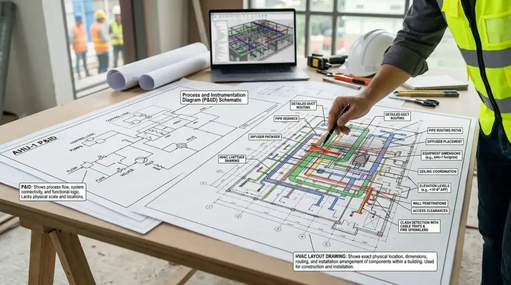
A P&ID, or Piping and Instrumentation Diagram, represents how a system operates. It focuses on process flow, control logic, equipment interaction, and system functionality. HVAC layout drawings focus on geometry, dimensions, routing, and physical coordination with architectural and structural elements.
Engineering teams in industries like construction, oil and gas, healthcare, manufacturing, and commercial real estate depend on both drawing types during project execution. A facilities management department reviewing chilled water performance uses a P&ID to understand valve sequencing and instrumentation. The same department uses HVAC layout drawings to identify duct locations, pipe routing, and equipment placement inside a building.
In corporate environments, drawing interpretation forms part of technical competency frameworks for mechanical engineers, CAD technicians, maintenance planners, and project managers. Organisations often identify skill gaps in drawing interpretation during project delays, commissioning failures, or coordination conflicts between contractors.
Technical training programmes address these gaps through structured learning modules. Teams typically complete 20 to 40 hours of instruction covering schematic interpretation, AutoCAD drafting standards, HVAC systems, plumbing integration, and documentation control procedures.
How does a P&ID work inside an HVAC or plumbing system?
A P&ID works by representing system operations through symbols, line types, instrumentation tags, and process connections. It explains how fluids, air, controls, and equipment interact during system operation, maintenance, and troubleshooting within commercial and industrial facilities.
A P&ID does not show exact physical dimensions. Instead, it communicates operational logic. Mechanical systems rely on this logic during installation, commissioning, maintenance, and safety reviews.
For example, a chilled water system P&ID includes:
- Chillers
- Pumps
- Control valves
- Flow meters
- Pressure gauges
- Expansion tanks
- Isolation valves
- Temperature sensors
Each component follows standardised symbols and tagging conventions. Engineering teams interpret these symbols using international drafting standards such as ISA standards and ISO documentation practices.
A facilities operations team troubleshooting pressure imbalance in a hospital HVAC system uses the P&ID to identify:
- Water flow direction
- Valve positions
- Instrumentation points
- Pump sequencing logic
- Emergency shutdown connections
This process reduces troubleshooting time and improves coordination between maintenance and engineering departments.
Corporate technical training programmes often include simulation-based exercises where participants diagnose faults using P&IDs. These exercises measure competency through assessment metrics such as:
- Drawing interpretation accuracy
- Time-to-diagnosis
- Error reduction rates
- Maintenance response efficiency
Training departments use these metrics to evaluate workforce readiness and operational capability.
What does an HVAC layout drawing show that a P&ID does not?
An HVAC layout drawing shows the exact physical location, dimensions, routing, and installation arrangement of mechanical components within a building. A P&ID does not provide spatial coordination or construction-level placement information required for installation and site execution.
HVAC layout drawings support construction teams, BIM coordinators, site supervisors, and installers during physical implementation.
A layout drawing includes:
- Duct routing
- Pipe routing
- Diffuser placement
- Equipment dimensions
- Ceiling coordination
- Wall penetrations
- Elevation levels
- Access clearances
For example, a commercial office project requires coordination between HVAC ducts, plumbing pipes, fire protection systems, and electrical cable trays. Layout drawings allow multidisciplinary teams to detect clashes before installation begins.
Building Information Modelling workflows depend heavily on accurate layout drawings. Organisations implementing BIM-based project delivery report measurable reductions in rework costs and installation conflicts because layout drawings support digital coordination processes.
P&IDs cannot replace layout drawings because they serve different operational purposes. A P&ID explains what the system does. An HVAC layout shows where the system is physically located.
In workforce development programmes, trainers often compare both drawings side by side. This approach improves spatial reasoning and system-thinking capabilities among technical staff.
How do organisations train employees to interpret P&IDs and HVAC drawings?
Organisations train employees through structured technical learning programmes combining theory, AutoCAD practice, schematic analysis, simulations, and project-based assessments. Training delivery often includes workshops, hybrid learning, and software-based exercises aligned with real operational documentation standards.
Engineering and construction organisations face recurring competency gaps in technical drawing interpretation. These gaps affect project timelines, commissioning quality, safety compliance, and maintenance efficiency.
Learning and Development teams address these challenges through competency-based training structures that include:
Foundation-Level Technical Concepts
Employees learn:
- Mechanical system fundamentals
- HVAC process flow
- Plumbing design principles
- Drawing standards
- Equipment identification
- Instrumentation symbols
This stage establishes a common technical vocabulary across departments.
AutoCAD-Based Drawing Interpretation
Participants analyse:
- P&IDs
- Schematic drawings
- Isometric drawings
- HVAC layouts
- Single-line diagrams
Training often uses real project documentation instead of generic templates. This improves transferability to workplace tasks.
Applied Simulation and Scenario Learning
Corporate training environments increasingly use case-based learning methodologies. Teams review simulated engineering scenarios involving:
- Pump failures
- Valve sequencing issues
- Air balancing problems
- Coordination clashes
- Commissioning defects
Assessment criteria include:
- Drawing accuracy
- Fault identification speed
- Documentation compliance
- Team collaboration performance
Many organisations integrate online modules with instructor-led workshops. Hybrid learning formats improve participation rates across geographically distributed teams.
When organisations evaluate advanced technical drafting skills, many teams review how schematic interpretation differs from operational process documentation through resources discussing:
How AutoCAD HVAC training distinguishes P&IDs from schematic drawings. This stage aligns awareness-level understanding with implementation-focused evaluation.
For deeper insight, enrol in:
AutoCAD HVAC and Plumbing Design Training Course.
What are the key components included in a standard P&ID?
A standard P&ID includes process equipment, piping systems, instrumentation, control devices, valves, flow direction indicators, and identification tags. These components create a complete operational map that engineering teams use for commissioning, maintenance, compliance, and troubleshooting activities.
Each component serves a specific operational function.
Equipment Symbols
Equipment symbols represent assets such as:
- Boilers
- Chillers
- Pumps
- Cooling towers
- Heat exchangers
- Air handling units
These symbols standardise communication between engineering disciplines.
Piping Information
Pipe lines include indicators for:
- Pipe size
- Flow direction
- Connection points
- Material classifications
- Service identification
This information supports maintenance planning and operational continuity.
Instrumentation and Control Devices
Instrumentation defines how systems are monitored and controlled.
Examples include:
- Temperature indicators
- Pressure transmitters
- Flow controllers
- Level sensors
- Motorised valves
Control logic within a P&ID helps operators understand automation sequences and emergency shutdown procedures.
Identification Tags
Tagging systems provide traceability across facilities management systems, maintenance software, and asset registers.
For example:
- P-101 for pumps
- XV-201 for valves
- TI-301 for temperature indicators
Consistent tagging improves communication accuracy across departments.
Why do businesses require both P&IDs and HVAC layout drawings during projects?
Businesses require both drawing types because operational understanding and physical installation involve different technical requirements. P&IDs support system functionality and process control, while HVAC layouts support construction coordination, installation sequencing, and spatial planning across multidisciplinary project teams.

Large-scale projects involve multiple stakeholders, including:
- Mechanical engineers
- Electrical engineers
- Contractors
- Procurement teams
- Facilities managers
- Health and safety officers
- Commissioning specialists
Each stakeholder depends on different information types.
Procurement teams use P&IDs to identify equipment specifications and instrumentation requirements. Installation contractors rely on layout drawings to coordinate site execution.
Commissioning teams compare operational sequences shown in P&IDs against installed systems shown in layout drawings. Facilities management departments use both during long-term asset maintenance.
Businesses implementing structured documentation workflows experience measurable improvements in:
- Project coordination efficiency
- Installation accuracy
- Maintenance response times
- Regulatory compliance
- Documentation consistency
These outcomes support operational resilience and lifecycle asset management strategies.
What common misconceptions create problems when teams use P&IDs and HVAC drawings?
The most common misconception is assuming P&IDs and HVAC layout drawings perform the same function. This misunderstanding creates coordination errors, incorrect installations, delayed commissioning, and communication breakdowns between engineering, operations, and construction teams.
Many new technical employees interpret a P&ID as a construction drawing. This creates installation mistakes because P&IDs do not provide dimensions or exact spatial relationships.
Another common issue involves inconsistent symbol interpretation. Organisations without standardised training often experience communication gaps between departments and contractors.
Additional problems include:
- Outdated documentation
- Missing revision control
- Non-standard tagging systems
- Poor AutoCAD competency
- Lack of interdisciplinary coordination
These issues directly affect operational KPIs such as:
- Rework percentage
- Downtime duration
- Maintenance costs
- Commissioning delays
- Safety incident rates
Learning and Development departments increasingly implement technical competency frameworks to standardise engineering documentation skills across teams.
Effective programmes include:
- Practical assessments
- Real project examples
- CAD-based exercises
- Documentation reviews
- Cross-functional workshops
This structured approach improves workforce consistency and reduces operational risk.
How do P&ID and HVAC drawing skills support workforce development strategies?
P&ID and HVAC drawing skills support workforce development by improving technical communication, operational efficiency, documentation accuracy, and cross-functional collaboration. Organisations integrate these competencies into engineering capability frameworks, succession planning models, and technical certification pathways.
Engineering and facilities teams operate in environments requiring high documentation accuracy. Errors affect project delivery, safety compliance, and operational continuity.
Organisations therefore treat drawing interpretation as a measurable technical competency rather than a basic drafting skill.
Workforce development programmes often align technical training with broader business objectives such as:
- Reducing commissioning delays by 15%
- Improving maintenance efficiency by 20%
- Lowering rework costs during construction phases
- Standardising documentation practices across sites
- Strengthening engineering succession pipelines
Training delivery formats vary according to organisational structure.
Examples include:
- Instructor-led workshops for engineering teams
- Online AutoCAD modules for remote employees
- Hybrid programmes for multinational operations
- Project-based assessments for technical supervisors
- Simulation labs for maintenance personnel
Industry-driven learning environments focus on practical application rather than theoretical memorisation. Employees work with realistic project documentation, operational scenarios, and collaborative review exercises.
Discover More from Our Guide Library:
How Is Hot Water and Heating System Design Created in AutoCAD Drawings?
What Are Common HVAC AutoCAD Drawing Errors That Junior Engineers Make?
This methodology strengthens technical confidence, improves interdepartmental coordination, and supports long-term operational performance.
What is included in an AutoCAD HVAC and Plumbing Design Training Course?
The Imperial Corporate Training Institute AutoCAD HVAC and Plumbing Design Training Course typically covers HVAC drafting, plumbing layouts, duct sizing, piping systems, P&IDs, and schematic drawing interpretation. Participants also learn AutoCAD tools used in mechanical building services projects.
Who should attend an AutoCAD HVAC and Plumbing Design Training Course?
The AutoCAD HVAC and Plumbing Design Training Course is suitable for mechanical engineers, CAD technicians, MEP professionals, project supervisors, and facilities teams. Imperial Corporate Training Institute designs the training for professionals involved in HVAC system design, technical drafting, and building services coordination.
How does AutoCAD HVAC training improve workplace performance?
AutoCAD HVAC training improves drawing accuracy, coordination between engineering teams, and project documentation quality. Organisations using structured technical training often reduce design errors, rework costs, and installation delays in construction and facilities management projects.
What is the difference between HVAC layout drawings and P&IDs in AutoCAD training?
HVAC layout drawings show the physical placement of ducts, pipes, and equipment within a building, while P&IDs explain operational flow and control systems. The AutoCAD HVAC and Plumbing Design Training Course teaches how both drawing types of support installation, commissioning, and maintenance activities.