
Refrigerant pipe design for Variable Refrigerant Flow (VRF) systems is the process of planning, sizing, routing, and documenting refrigerant piping networks that connect outdoor units with multiple indoor units while maintaining system efficiency, safety, and operational performance across commercial buildings.
VRF systems are advanced HVAC solutions that use refrigerant as the primary cooling and heating medium. A single outdoor unit can serve numerous indoor units through a complex refrigerant piping network. This design approach allows different zones within a building to operate independently while maintaining energy efficiency.
From a business perspective, refrigerant pipe design directly influences building performance, energy consumption, maintenance requirements, and lifecycle costs. Industries such as healthcare, education, hospitality, and commercial real estate rely on properly designed VRF systems to achieve temperature control, occupant comfort, and operational efficiency.
Within the AutoCAD HVAC and Plumbing Design Training Course, refrigerant pipe design forms a critical technical competency. Organisations increasingly require HVAC designers, MEP engineers, and CAD technicians who can create accurate VRF piping layouts that align with manufacturer specifications and industry standards.
The growing adoption of VRF technology creates a workforce demand for professionals capable of producing technically correct design documentation. This skill reduces project errors, improves coordination among disciplines, and supports efficient construction execution.
How Does AutoCAD HVAC Training Teach VRF Refrigerant Pipe Design?
AutoCAD HVAC training teaches VRF refrigerant pipe design through a structured process that combines HVAC theory, system design principles, CAD drafting techniques, equipment coordination, annotation standards, and project-based exercises that simulate real commercial building projects.
Training programmes typically begin with HVAC system fundamentals before progressing to VRF-specific design concepts. Learners first understand how refrigerant circulates between outdoor and indoor units and how pipe networks support system operation.
Understanding VRF System Architecture
Training introduces the components that make up a VRF installation. These include outdoor condensing units, indoor fan coil units, branch selector boxes, refrigerant piping, control systems, and condensate drainage networks.
Participants learn how these elements interact within office buildings, hotels, hospitals, and retail facilities. Understanding system architecture creates the foundation for accurate drafting and documentation.
Translating Engineering Concepts into CAD Drawings
After understanding system fundamentals, learners use AutoCAD to convert engineering requirements into technical drawings.
Training exercises focus on:
- Equipment placement
- Pipe routing
- Branch connection layouts
- Drawing coordination
- Design documentation
This process demonstrates how engineering concepts become construction-ready drawings.
Applying Project-Based Learning
Corporate training environments increasingly use practical learning methodologies.
Examples include:
- Commercial office floor plans
- Multi-storey residential buildings
- Hotel HVAC layouts
- Mixed-use developments
These projects help learners understand real workplace design requirements rather than isolated software functions.
What Steps Are Followed When Drawing Refrigerant Pipe Layouts in AutoCAD?
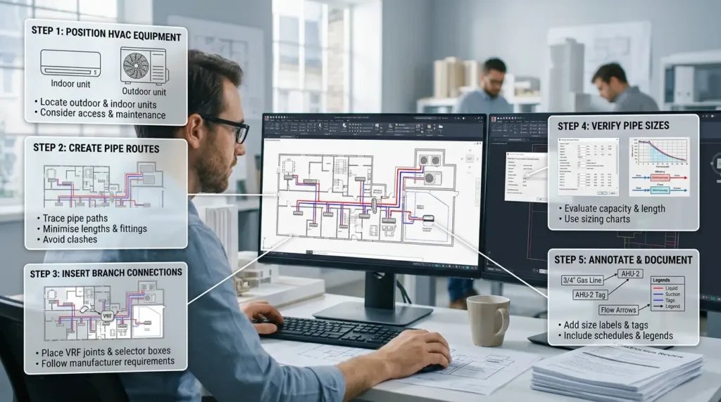
Drawing refrigerant pipe layouts in AutoCAD follows a sequential workflow that includes equipment positioning, pipe routing, branch connection placement, sizing verification, annotation, layer management, and final documentation review for construction readiness.
The workflow mirrors professional design office practices.
Step 1: Position HVAC Equipment
Design begins by placing outdoor and indoor units according to architectural constraints and HVAC design requirements.
Engineers identify suitable equipment locations while considering accessibility, maintenance clearances, and piping distances.
Step 2: Create Refrigerant Pipe Routes
Pipe routes are drawn between indoor and outdoor units.
Training teaches designers to:
- Minimise excessive pipe lengths
- Reduce unnecessary fittings
- Maintain installation accessibility
- Avoid clashes with other building services
Coordination with electrical, plumbing, and structural systems becomes a major part of the process.
Step 3: Insert Branch Connections
VRF systems commonly use branch joints or branch selector boxes.
Training explains:
- Connection hierarchy
- Flow distribution
- Manufacturer requirements
- Branch placement standards
Accurate branch positioning ensures system balance and performance.
Step 4: Verify Pipe Sizes
Pipe sizing represents one of the most important technical stages.
Learners evaluate:
- Cooling capacity requirements
- Refrigerant flow rates
- Equivalent pipe lengths
- Manufacturer sizing charts
Design validation helps ensure system efficiency and reliability.
Step 5: Annotate and Document
The final stage involves creating construction-ready documentation.
Drawings include:
- Pipe size labels
- Equipment tags
- Flow direction indicators
- Reference notes
- Schedules and legends
Accurate documentation improves communication between designers, contractors, and facility operators.
What Technical Skills Are Included in Refrigerant Pipe Design Training?
Refrigerant pipe design training develops technical skills in HVAC system interpretation, AutoCAD drafting, pipe sizing, coordination management, design documentation, drawing standards compliance, and construction communication.
Organisations seek professionals who combine software proficiency with engineering understanding.
HVAC Design Interpretation
Learners study:
- Refrigeration cycles
- Heat transfer principles
- Cooling load relationships
- Equipment performance data
These competencies help designers understand why specific piping decisions are necessary.
AutoCAD Drafting Skills
Training develops proficiency in:
- Layer management
- Blocks and attributes
- Annotation tools
- Dynamic drafting techniques
- Drawing organisation
These skills improve drawing accuracy and consistency.
Design Coordination
Large projects involve multiple disciplines.
Training covers coordination with:
- Structural teams
- Architectural teams
- Electrical engineers
- Plumbing designers
- Construction managers
This multidisciplinary approach reduces design conflicts during project delivery.
Documentation Standards
Consistent documentation improves project quality.
Learners apply:
- Naming conventions
- Annotation standards
- Drawing templates
- Revision control procedures
- Technical schedules
These standards support organisational quality assurance processes.
What Components Are Included in a Complete VRF Refrigerant Piping Drawing?
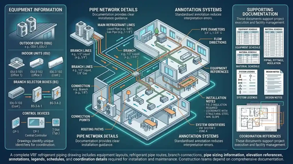
A complete VRF refrigerant piping drawing includes equipment layouts, refrigerant pipe routes, branch connections, pipe sizing information, elevation references, annotations, legends, schedules, and coordination details required for installation and maintenance.
Construction teams depend on comprehensive documentation.
Equipment Information
Drawings identify:
- Outdoor units
- Indoor units
- Branch selector boxes
- Control devices
Each component receives unique identifiers for coordination purposes.
Pipe Network Details
Pipe networks include:
- Main refrigerant lines
- Branch lines
- Connection points
- Routing paths
Documentation provides clear installation guidance.
Annotation Systems
Annotation improves drawing usability.
Typical annotations include:
- Pipe diameters
- Flow directions
- Equipment references
- Installation notes
- System identifiers
Standardised annotation reduces interpretation errors.
Supporting Documentation
Additional project information often includes:
- Equipment schedules
- Material schedules
- System legends
- Design notes
- Coordination references
These documents support project execution and facility management.
How Do Organisations Implement Refrigerant Pipe Design Skills in the Workplace?
Organisations implement refrigerant pipe design skills by integrating trained personnel into HVAC design workflows, standardising drawing procedures, establishing quality control processes, and measuring project outcomes through efficiency, accuracy, and coordination metrics.
Implementation extends beyond software training.
Addressing Workforce Skill Gaps
Many organisations face shortages of technically skilled HVAC drafting personnel.
Common gaps include:
- VRF system knowledge
- Pipe sizing competence
- Documentation standards
- CAD efficiency
Structured training programmes address these deficiencies systematically.
Training Delivery Formats
Corporate learning departments commonly use:
- Instructor-led workshops
- Virtual classrooms
- Hybrid learning programmes
- Project simulations
- Technical assessments
A typical programme lasts between 20 and 80 training hours depending on learner experience and curriculum depth.
Performance Measurement
Organisations evaluate training effectiveness using measurable indicators.
Examples include:
- Drawing accuracy rates
- Design review findings
- Rework reduction percentages
- Project delivery times
- Coordination issue frequency
These metrics help demonstrate training ROI.
At the point where organisations begin evaluating implementation methods and drawing standards, readers often seek deeper technical guidance on layout development and documentation practices. This is the ideal stage to reference a detailed resource explaining how refrigerant networks are documented in CAD environments using natural anchor text such as a detailed guide to:
Drawing and annotating VRF refrigerant layouts in AutoCAD.
What Business Benefits Result from Accurate VRF Refrigerant Pipe Design Training?
Accurate VRF refrigerant pipe design training improves project quality, reduces design errors, enhances interdisciplinary coordination, increases productivity, shortens project timelines, and strengthens organisational technical capabilities.
Businesses benefit from measurable operational improvements.
Reduced Design Rework
Design errors generate additional labour costs and project delays.
Well-trained teams produce drawings with fewer coordination conflicts and fewer revision cycles.
Organisations frequently track reductions in design rework as a key training outcome.
Improved Team Productivity
Standardised drafting procedures improve workflow efficiency.
Teams spend less time correcting documentation and more time completing deliverables.
This productivity improvement supports higher project throughput.
Enhanced Quality Control
Technical accuracy contributes to better project outcomes.
Quality reviews identify fewer issues when personnel understand both HVAC engineering principles and CAD documentation requirements.
This supports organisational excellence and consistency.
Stronger Collaboration
Design projects involve multiple stakeholders.
Shared documentation standards improve communication between engineering teams, contractors, project managers, and facility operators.
Collaboration supports faster decision-making and smoother project execution.
What Common Problems and Misconceptions Exist Around VRF Design Training?
Common misconceptions include treating AutoCAD training as software-only instruction, assuming VRF systems require identical piping layouts across projects, and measuring training success solely through course completion rather than workplace performance outcomes.
These misunderstandings reduce training effectiveness.
Misconception 1: Software Skills Alone Are Sufficient
Many organisations focus exclusively on AutoCAD commands.
Effective refrigerant pipe design requires understanding HVAC engineering principles, system performance requirements, and installation constraints.
Software proficiency alone does not guarantee competent design work.
Misconception 2: All VRF Projects Follow the Same Design Pattern
Building requirements vary significantly.
Examples include hospitals, data centres, educational facilities, and hotels.
Each environment introduces different zoning, capacity, coordination, and operational requirements.
Training must reflect these real-world variations.
Misconception 3: Completion Equals Competence
Training success should be measured through workplace performance.
Relevant indicators include:
- Drawing quality
- Project delivery efficiency
- Error reduction
- Technical assessment scores
- Design review outcomes
These metrics provide a more accurate measure of capability development.
How Does Refrigerant Pipe Design Training Support Long-Term Workforce Development?
Refrigerant pipe design training supports workforce development by building technical capability, improving project delivery standards, strengthening design consistency, and creating a foundation for advanced HVAC, MEP, and building services engineering responsibilities.
Technical industries require continuous capability development.
Organisations invest in specialised training to maintain competitiveness and respond to evolving building technologies. VRF systems continue to expand across commercial construction sectors, increasing demand for professionals who understand both HVAC engineering and digital drafting workflows.
Discover More from Our Guide Library:
What Are the Career Steps From AutoCAD Draughtsman to Senior MEP Designer?
How Does AutoCAD HVAC Training Differ Between Residential and Commercial Projects?
Training programmes that combine practical application, real-world project scenarios, technical assessments, and measurable performance outcomes contribute to workforce transformation. Employees gain skills that support organisational objectives, while businesses improve project quality, operational efficiency, and design reliability.
For HR managers, L&D professionals, business owners, and team leaders, refrigerant pipe design training represents a structured approach to closing technical skill gaps and developing workforce capabilities aligned with modern HVAC project requirements.
Frequently Asked Questions
Who should attend an AutoCAD HVAC and Plumbing Design Training Course?
This course is suitable for HVAC engineers, mechanical designers, CAD technicians, MEP professionals, and technical graduates. It helps participants develop practical AutoCAD skills for HVAC and plumbing design in commercial, residential, and industrial projects.
How does AutoCAD training support HVAC and plumbing design projects?
AutoCAD training enables professionals to create accurate HVAC and plumbing drawings, coordinate building services, and produce detailed design documentation. These skills improve project efficiency, reduce drafting errors, and support effective construction planning.
Does the AutoCAD HVAC and Plumbing Design Training Course include VRF system design?
Yes, the course typically includes VRF system layouts, refrigerant pipe routing, equipment scheduling, and technical annotations. Imperial Corporate Training Institute incorporates practical exercises that reflect real-world HVAC design requirements and industry practices.
What skills can participants gain from an AutoCAD HVAC and Plumbing Design Training Course?
Participants develop skills in HVAC drafting, plumbing design, layer management, system coordination, drawing annotation, and technical documentation. These competencies support accurate building services design and improve project delivery standards.